
You've got the building package, a cleared site, and a concrete contractor asking how thick you want the slab. On an Atlanta-area metal building, that question comes too early. The right concrete foundation for a metal building starts with column reactions, soil conditions, wind uplift, drainage, and the way you'll use the finished space.
A four-inch residential-style slab may suit a light garage on competent soil. It may be the wrong answer for a warehouse, equipment building, or site with expansive clay. The foundation has to support concentrated steel-column loads, resist uplift, keep anchor bolts precisely positioned, and provide a dry, stable floor for years.
Why the Foundation Choice Matters for a Metal Building
A 60-by-100-foot steel warehouse in Fulton County can look straightforward from the road. Red clay, however, changes the conversation. If the owner assumes a flat slab before reviewing the soil profile and the steel supplier's reaction sheet, that first decision can affect excavation, perimeter forming, plumbing rough-ins, finished-floor elevation, anchor placement, and the erection schedule.
Metal buildings transfer much of their structural demand through individual columns, not continuously through exterior walls. A life-cycle assessment of prefabricated industrial buildings measured foundation excavation at 0.173 m³ per square meter, foundation steel at 7.13 kg per square meter, and model foundation concrete at 0.0504 m³ per square meter of building area, demonstrating that the foundation stage is a meaningful part of material demand, not a minor add-on (MDPI life-cycle assessment). A steel system can also weigh only 2 to 5 pounds per square foot, which makes wind uplift a serious foundation design issue (ASCE engineering article).
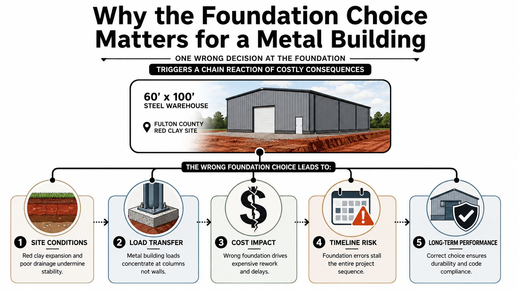
On that type of Fulton County site, the early questions should be practical:
- What does the soil support? Red clay may need improved drainage, engineered fill, or a deeper system.
- Where do the reactions land? The vendor's column data determines footing width, reinforcing, and anchorage.
- How will water leave the site? A slab edge that sits below surrounding grade invites moisture problems.
- What must pass through the floor? Plumbing, electrical sleeves, drains, and door thresholds have to be set before the pour.
- What will the building hold? Passenger vehicles, forklifts, stored materials, and machinery create different floor demands.
The cost difference between a four-inch residential-style slab and a six-inch fiber-mesh commercial slab with a turned-down edge can be substantial, but the bigger risk is choosing the wrong system. Re-drilling anchors, adding piers after forming, or re-engineering column base plates costs more than resolving the design before concrete arrives.
Field rule: A slab thickness is an output of the building and site data. It isn't the foundation design by itself.
The Main Foundation Types Explained
Five systems commonly appear beneath metal buildings. Each solves a different load-transfer problem, and the erector's reaction sheet usually narrows the choices before a concrete crew sets forms.
Slab-on-grade with a thickened edge
This is the floor-and-foundation combination most owners picture. The interior slab rests on prepared sub-base, while a thickened perimeter edge or monolithic turndown carries frame and edge reactions. It fits many light commercial buildings, storage structures, and workshops on competent soil.
A common benchmark for residential and light commercial buildings is a 4-inch interior slab with a perimeter edge about 12 to 18 inches deep and 12 to 18 inches wide. Heavier use often moves to a 6-inch slab (Viking Metal Garages foundation guidance).
Isolated spread footings
Think of these as individual stools under each structural column. A separate slab-on-grade can remain mostly a floor, while each footing spreads concentrated reactions into the soil. This arrangement earns its place when column loads are heavy or when the engineer wants the floor slab independent of the primary frame supports.
Continuous strip footings
A continuous footing runs beneath a wall, perimeter haunch, or stem wall. It works where the building has a substantial perimeter load path or where a raised edge is needed to establish finished-floor height and resist lateral forces.
Pier and grade-beam systems
Piers act like stilts. They extend through unsuitable near-surface material or an active clay zone to reach better support below. Grade beams can connect the piers, tie column bases together, and improve resistance to lateral movement and uplift. This system suits deep fill, expansive soil, uneven terrain, and some agricultural buildings.
Structural slabs and pier mats
A structural slab or reinforced pier mat is appropriate when the floor itself carries major equipment, crane reactions, mezzanine loads, or other concentrated forces. It isn't a thicker driveway slab. The reinforcing, joints, support conditions, and load path need engineering.
| Foundation Type | Best Fit | Typical Loads | Soil Suitability | Relative Cost |
|---|---|---|---|---|
| Slab-on-grade with thickened edge | Garages, storage, light commercial | Floor loads and moderate column reactions | Competent, well-compacted soil | Lower to moderate |
| Isolated spread footings | Larger frames and heavier columns | Concentrated column reactions | Suitable bearing soil at footing depth | Moderate |
| Continuous strip footing | Perimeter walls and raised edges | Line loads and lateral restraint | Stable perimeter soils | Moderate |
| Pier and grade beam | Expansive clay, deep fill, high uplift | Column reactions transferred deeper | Poor surface soils with reliable deeper support | Moderate to high |
| Structural slab or pier mat | Cranes, mezzanines, equipment | High point and distributed loads | Engineer-determined | High |
For a commercial project, review the scope of commercial foundation concrete before selecting a crew. The contractor should understand how the structural system, site preparation, and concrete work operate as one package.
Loads, Soil, Frost Depth, and Anchorage
A foundation engineer doesn't size a footing from building dimensions alone. Four load categories shape the design:
- Dead load: Steel framing, roof panels, wall panels, insulation, and permanent attachments push downward through the columns.
- Live load: Occupants, stored goods, vehicles, and equipment add use-related demand.
- Snow load: Usually modest in much of Georgia, but still part of the design basis where applicable.
- Wind load: Wind can push laterally and create uplift that tries to pull the building away from its anchors.
A light commercial reaction sheet may show column reactions in the 20- to 80-kip range, depending on the frame and load combination. The footing must resist the vertical reaction, horizontal force, overturning effects, and uplift at that specific base. That's why a small steel base plate can require a substantial concrete element below it.
Soil controls footing width
Soil bearing capacity describes how much pressure the ground can accept without excessive settlement. 1,500 to 3,000 pounds per square foot is a common metro Atlanta benchmark, but the site investigation can change the design quickly. A boring may reveal fill, soft clay, groundwater, or stronger material at depth.
Bearing capacity generally drives footing area and width more directly than concrete thickness. If the soil supports less pressure, the engineer may widen the footing, add reinforcing, improve the sub-base, or move the load to piers. Increasing slab thickness alone doesn't correct weak soil beneath the footing.
Frost and anchor behavior
Frost depth is negligible across most of Georgia, but higher elevations and northern mountain areas still require local confirmation. An unheated barn can need a frost-protected shallow foundation with insulation details even where a heated slab would be treated differently.
Anchor bolts are sized for the reactions, not guessed from a standard sketch. Diameter, embedment, hook or head geometry, spacing, and concrete edge distance all affect pullout and shear resistance. The building engineer and foundation designer must use the same load data.
| Design Factor | Typical Range | Foundation Impact | Common Mistake |
|---|---|---|---|
| Column reaction | 20 to 80 kips for light commercial frames | Sets footing area, reinforcing, and anchorage | Bidding from building size alone |
| Soil bearing | 1,500 to 3,000 psf in metro Atlanta benchmarks | Controls footing width and settlement risk | Treating every clay site alike |
| Frost condition | Essentially zero in most Georgia locations | Affects footing depth and insulation details | Ignoring elevation and building heat |
| Wind uplift | May govern a lightweight steel structure | Increases concrete mass, embedment, and tie requirements | Designing only for downward load |
Typical Dimensions and Reinforcement Guidance
A 4-inch slab with a 12-inch turned-down edge can be a sensible arrangement for a 30-by-40-foot shop with light storage, modest vehicle use, and verified support beneath the perimeter. It isn't a universal answer for a 60-by-120-foot warehouse, where frame reactions, doors, traffic, storage, and uplift can demand isolated footings, a thicker slab, or both.
The reinforcing plan should follow the load path. Light work may use fiber reinforcement or a conventional reinforcing grid, while heavier applications may add bars at column lines, thickened edges, equipment pads, and openings. Rebar must be supported at the proper elevation. Steel lying on the sub-base doesn't provide the intended crack-control or structural benefit.
| Use Case | Slab Thickness | Thickened Edge / Footing | Reinforcement | Typical Column Reaction |
|---|---|---|---|---|
| Residential garage or light storage | 4 inches | 12 to 18 inches deep and wide at edge | Fiber reinforcement or light reinforcing grid | Light to moderate |
| Small workshop | 4 to 6 inches | Turned-down edge, with local thickening as needed | Reinforcing grid and possible fiber reinforcement | Around 10 kip |
| Light commercial building | 6 inches | Isolated or continuous footings as engineered | Heavier bar grid, often with fiber reinforcement | Around 30 kip |
| Warehouse or equipment building | 6 inches or more | Larger spread footings, piers, or grade beams | Heavier bar sizes and closer spacing | Around 50 kip or higher |
| Crane, mezzanine, or machinery area | Engineered structural slab | Pier mat or dedicated equipment footings | Structural reinforcing designed for point loads | Engineer-determined |
As reactions climb from 10 kip to 50 kip, the engineer may widen footing dimensions, increase reinforcing, deepen local bases, and connect isolated supports with grade beams. Typical project layouts can include footing diameters from 24 to 48 inches, pier shafts from 12 to 24 inches, and continuous footing widths from 16 to 36 inches, but those are design ranges, not automatic specifications.
A detail such as #4 rebar at 18-inch centers may suit a lighter commercial arrangement. A heavier warehouse can move toward #5 rebar on 12-inch grids, welded wire mat, or supplemental bars around columns and openings. Fiber reinforcement helps control plastic shrinkage and distributes small cracks, but it doesn't replace structural reinforcing where the engineer requires bars for bending, shear, uplift, or concentrated reactions.
Moving from four to six inches increases concrete volume and can raise installed cost. The right comparison isn't slab price alone. It's the cost of the complete system, including excavation, footing concrete, reinforcing, forms, anchor coordination, and inspection.
For the concrete placement scope, review commercial poured concrete and compare the proposed reinforcement schedule against the stamped foundation drawings.
Coordinating Anchor Bolts and Column Reactions
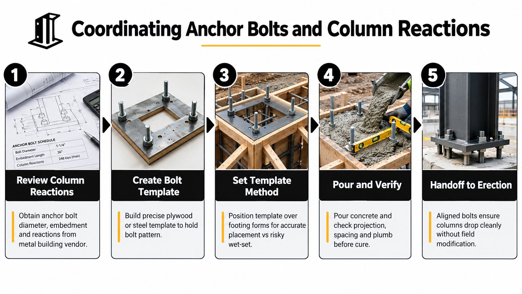
Anchor bolts are the mechanical handshake between the steel frame and the concrete. If the bolt pattern doesn't match the column base plate, the erector can't force the frame into place without compromising the connection or creating expensive field work.
A practical handoff looks like this:
- Obtain the approved reaction sheet and anchor plan. The vendor should provide the bolt diameter, embedment, projection, spacing, base-plate dimensions, and design reactions from the approved drawings.
- Compare the plan with the permit set. Check grid lines, column centers, slab edges, door openings, drains, and any thickened areas.
- Build a rigid template. A plywood or steel jig holds the bolt pattern while the forms and reinforcing are installed.
- Set and verify before the pour. Check bolt spacing, plumb, projection, elevation, and clearance from reinforcing.
- Document the handoff. The erector should receive a foundation that matches the approved layout, not a field interpretation.
Common anchor sizes may range from one-half inch to one inch, with embedment commonly running 12 to 18 inches and projection about 2 to 4 inches, but those values must follow the stamped drawings and uplift design. The numbers are not a substitute for the vendor's connection requirements.
Wet-set installation places J-bolts or headed studs directly into fresh concrete and can work well when the crew has a rigid template and a carefully controlled pour. Template or sleeve methods can offer adjustment advantages in selected systems, but they still require an approved detail and proper inspection. Improvising either method is a poor trade.
The most expensive change order often starts with a bolt that was set from an outdated drawing. The foundation contractor needs the final anchor-bolt plan before forming begins, and the steel supplier must be available to answer questions before concrete placement.
Drainage, Sub-Base, and Atlanta Site Conditions
A slab can be poured to the right thickness and still move, crack, or admit water if the site sends runoff toward it. Around Atlanta, humid weather, intense storms, red clay, and undocumented fill often combine beneath metal buildings. Concrete strength cannot correct a drainage path or a poorly compacted pad.
Build the sub-base around the soil profile and the building loads. Remove organic material, place suitable aggregate in controlled lifts, and compact the pad to 95% modified Proctor density. Complete underground utility routing before the pour, as outlined in this technical foundation guidance. Column reaction data and uplift loads also matter here, because weak or wet soil can require wider footings, improved fill, or a different drainage layout rather than a thicker slab.
Red clay sheds water slowly when compacted, while aggregate can drain quickly but still carry water toward the footing if the surrounding grade is wrong. On Fulton or DeKalb sites, I set the finish grade to send runoff away from the slab and keep the slab edge above nearby flow paths. A French drain belongs on the uphill side when groundwater or hillside runoff reaches the excavation. It should discharge to an approved outlet, not terminate beside the footing.
Details that protect the finished floor
Enclosed workshops, storage buildings, and coated floors need deliberate moisture control. Use a vapor retarder beneath the slab, seal utility penetrations, and keep perimeter drainage open. These measures reduce slab sweating, moisture migration, and corrosion around metal components.
Atlanta sites often look dry during forming and still hold water below the aggregate after a storm. Check the sub-base after compaction, correct soft spots before steel placement, and do not let a pump truck or concrete crew cover questionable fill. The site plan should control the grading detail, with the engineer resolving conflicts between soil conditions, drainage, and the metal building's support reactions.
Permits, Code, and Geotechnical Coordination
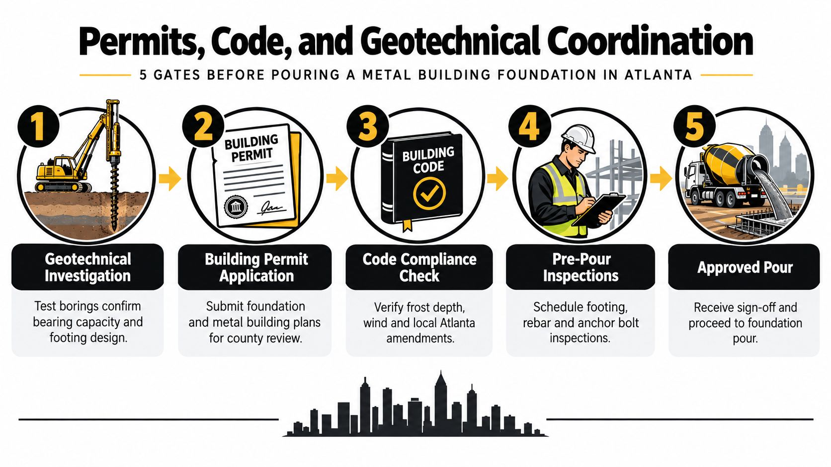
The permit process should begin before excavation, not after the footing trenches are open. The owner, building supplier, engineer, and contractor need one coordinated drawing set showing the site plan, foundation design, steel framing, anchor layout, drainage intent, and utility penetrations.
A workable sequence is:
- Investigate the soil. Obtain a geotechnical report where conditions are uncertain. If a formal investigation isn't required, confirm the county's accepted soil assumptions before sizing footings.
- Submit the permit package. Include the metal building drawings and the foundation documents prepared for the specific site.
- Confirm local design conditions. Verify wind requirements, drainage provisions, frost considerations, setbacks, and any Atlanta-area amendments.
- Schedule pre-pour inspections. Expect checks of footing excavation, reinforcing, vapor control, forms, and anchor-bolt placement before concrete covers the work.
- Pour after approval. Keep the inspection record and final anchor layout with the project file.
Metro Atlanta generally has minimal frost concerns, but higher-elevation areas and counties farther north can require different footing or insulation details. A heated slab and an unheated barn also don't have identical performance requirements, especially where shallow frost protection is part of the design.
The metal-building vendor supplies the anchor-bolt information for its frame. The foundation engineer incorporates that information into the permit drawings, and the concrete contractor builds from the approved set. If those documents disagree, stop before the pour.
Owners who want a practical checklist can browse concrete foundation inspections while confirming the exact requirements with the local building department and project engineer.
Choosing a Contractor and Your Next Steps
A metal building foundation is too specialized for a flatwork crew that only wants a square-foot price. The contractor should ask for the column reaction sheet before bidding, identify the assumed soil bearing value, review drainage and finished-floor elevation, and coordinate the anchor template with the building supplier.
Look for evidence in the proposal, not just confidence during the site visit:
- Comparable work: The contractor can describe recent metal garages, workshops, warehouses, or agricultural buildings completed in the Southeast.
- Document control: The bid identifies the drawing revision used for anchor bolts, reinforcing, and footing dimensions.
- Line-item scope: Excavation, sub-base, forming, reinforcing, anchorage, concrete placement, finishing, curing, testing, and cleanup are separated.
- Permit discipline: The crew won't pressure you to pour before permits and required inspections are complete.
- Insurance and risk management: Review practical guidance on contractors insurance from Select Insurance and ask the bidder for current certificates appropriate to the work.
Don't choose a contractor because a four-inch slab appears cheaper on paper. That number may exclude undercutting, compacted fill, isolated footings, anchor templates, drainage improvements, or reinforcing upgrades. A low bid that omits those items isn't comparable to a complete foundation proposal.
For an Atlanta project, gather the building address, intended use, dimensions, reaction data, anchor plan, and any existing soil information. If no soil investigation exists and the site contains fill, wet clay, slopes, or previous structures, ask the engineer whether testing is warranted before footing sizes are finalized.
Then request two or three bids with the same stamped drawings and a clear scope. You can send project details through the Atlanta Concrete Solutions contact page for a discussion of excavation, poured slabs, reinforcement, vapor control, drainage, and foundation installation.
Atlanta Concrete Solutions can coordinate excavation, soil preparation, reinforcement, vapor control, drainage planning, and poured slab or pier foundation work for commercial and industrial metal buildings. Bring your Atlanta site address, reaction sheet, and foundation drawings, then visit Atlanta Concrete Solutions to request a project conversation and quote.