
The most popular advice about rebar spacing for a concrete slab is also the least reliable: “Use a standard grid and you'll be fine.” That shortcut ignores the slab's thickness, vehicle loads, aggregate size, concrete cover, soil support, and control-joint layout. A patio, a residential driveway, a garage floor, and an industrial equipment pad may all be called slabs, but they don't share the same reinforcement requirements.
For Atlanta property owners, the practical question isn't “What's the universal rebar grid?” It's what spacing works for this slab, under these loads, on this prepared subgrade, with this joint plan? Rebar can help distribute forces and hold cracks tighter, but it won't compensate for poor drainage, weak support, late sawing, or a mat that settles onto the ground during placement.
The Myth of Universal Rebar Spacing
A universal rebar grid is convenient, but it is not a design standard. Spacing must match the slab's thickness, use, loads, support, and joint plan. A walkway, residential driveway, garage floor, and equipment pad can require different reinforcement layouts, even when they use the same concrete mix.
For Atlanta work, soil and drainage deserve equal attention. Poorly compacted fill, water beneath the slab, or delayed control joints can create cracking regardless of how neat the reinforcement grid looks. Rebar distributes tension and helps hold cracks tighter. It does not correct settlement or replace proper joint planning.
Why tighter isn't automatically stronger
Packing in more steel can create a placement problem. Fresh concrete needs enough room for aggregate and cement paste to flow around every bar. A crowded mat can prevent proper vibration, leaving voids or honeycombing. Steel that is not fully encased cannot transfer forces reliably and has greater exposure to corrosion.
Minimum clear spacing is the greater of the bar diameter, 1 inch, and one times the nominal maximum aggregate size, as summarized in the ACI slab detailing provisions. The controlling dimension depends on the selected materials and detailing. It is not a fixed visual grid that applies to every slab.
Field reality: A crowded mat that blocks consolidation can perform worse than a simpler, well-supported layout that gives concrete room to flow.
Reinforcement manages cracks, it doesn't erase them
Concrete shrinks as it dries and moves with temperature changes. Rebar helps distribute tension and keep cracks narrower, but some cracking remains a normal risk. Saw-cut timing, joint depth, drainage, and subgrade preparation all affect the result.
Joint planning should start before the bar schedule. Set the slab thickness, service loads, soil support, exposure, concrete cover, and control-joint layout first. Then choose bar size and spacing that meet the drawings and code-based limits while remaining practical for the crew to place and tie. In some slabs, a fiber hybrid can support crack control, but it still must be coordinated with the reinforcement and joint system rather than treated as a universal substitute.
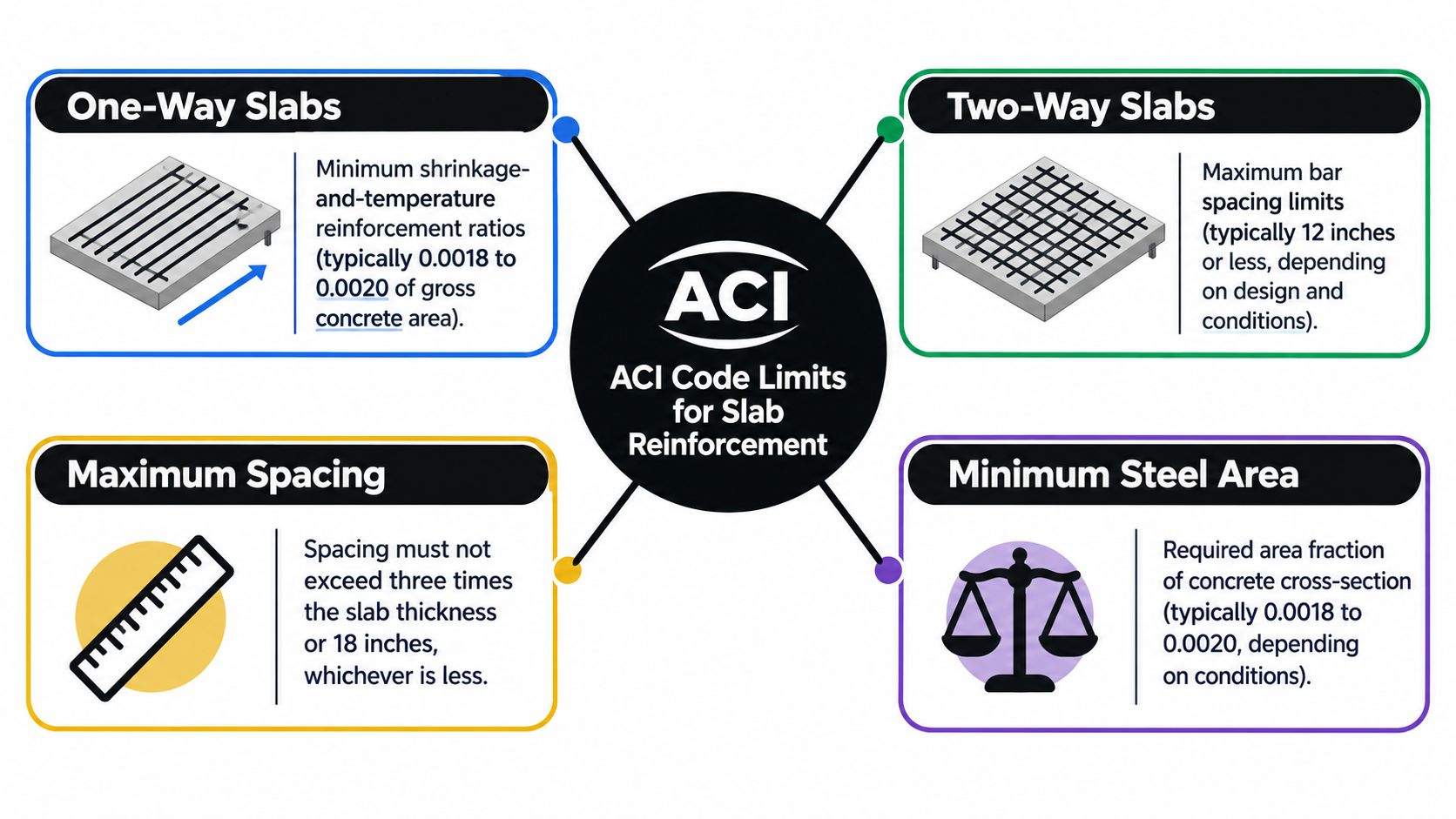
ACI Code Limits for Slab Reinforcement
ACI spacing limits depend on the reinforcement's function and the slab system. For nonprestressed reinforcement, ACI 318 limits flexural reinforcement spacing to the lesser of 3 times the slab thickness or 18 inches. Minimum clear spacing remains a separate check, governed by bar diameter, 1 inch, and the nominal maximum aggregate size. The slab detailing provisions provide the governing detailing framework, but they are not a substitute for the project design.
For one-way slabs, ACI 318 limits shrinkage-and-temperature reinforcement spacing to the lesser of 5 times the slab thickness or 18 inches. In two-way slab systems, the applicable thickness-based limit is the lesser of 2 times the slab thickness or 18 inches. The ACI detailing provisions for one-way and two-way systems summarize these distinctions.
Applying the thickness formula
The arithmetic is simple. Selecting the governing limit requires identifying the slab condition first.
- A 4-inch one-way slab: 5h equals 20 inches, so the 18-inch cap governs.
- A 3-inch one-way slab: 5h equals 15 inches, which is below the 18-inch cap. The maximum is 15 inches.
- A two-way slab: Compare 2h with the 18-inch cap. The smaller value governs.
These figures define maximum spacing, not the layout every slab should receive. The structural design may call for closer spacing, larger bars, added steel near concentrated loads, or a different reinforcement arrangement. Driveways with turning traffic, heavier vehicles, or weak support can need more reinforcement and better load distribution than a slab that merely passes the maximum-spacing check.
Thickness is only one check
Spacing does not determine the required steel area. Bar diameter, reinforcement direction, loads, concrete strength, cover, development, lap splices, slab edges, openings, and control joints also shape the design. A grid should not be approved solely because its spacing falls below a code limit.
Use these limits as boundary checks. The drawings or qualified design professional must establish whether the selected bars provide adequate strength and crack distribution for the actual slab, support conditions, and service loads. Joint timing and a coordinated fiber hybrid may improve crack control, but neither changes the governing reinforcement requirements.
Atlanta Driveway Thickness and Spacing Specs
A universal rebar grid is the wrong starting point for an Atlanta driveway. Begin with vehicle loads, slab thickness, soil support, drainage, and joint timing. A standard residential driveway is commonly 4 inches thick, according to Atlanta driveway guidance from Johns Creek Concrete. That thickness can suit ordinary passenger-vehicle use when the base, concrete, joints, and placement are properly handled.
Heavier vehicles and tight turning areas justify 5 or 6 inches. The added depth improves durability under greater wheel loads, as the same Atlanta driveway thickness guide explains. RVs, work trucks, trailers, and delivery vehicles create different demands from passenger cars, particularly where tires turn while nearly stationary.
A practical Atlanta specification conversation
Before requesting bids, resolve these points:
- Vehicle use. Identify passenger cars, trailers, work trucks, RVs, and delivery traffic. Give turning areas special attention because tires create twisting and concentrated stress.
- Slab thickness. Use 4 inches as the common residential baseline, then evaluate 5 or 6 inches where loading, vehicle type, or driveway geometry requires it.
- Concrete mix. A 4,000 PSI mix is a common residential driveway recommendation, as noted in Atlanta Concrete Solutions driveway guidance.
- Reinforcement design. Set bar size and spacing from the slab design, not an isolated internet rule. A code maximum only limits spacing. It does not prove that the selected steel suits the driveway.
- Subgrade and drainage. Remove or correct soft areas, compact supporting material, and direct water away from the slab. Steel cannot stabilize a base that moves beneath it.
For planning, residential driveway concrete installation information gives owners useful questions about excavation, thickness, reinforcement, joints, and finishing before bids are prepared.
Atlanta properties can have different fill, soil, and drainage conditions. A grid suitable for a firm, well-drained base may perform poorly over loose fill or repeatedly saturated subgrade. Select thickness and spacing together, then coordinate reinforcement with control-joint timing and any fiber hybrid. Joints placed too late or in the wrong locations can still leave a driveway vulnerable to random cracking, even when the steel spacing meets its code limit.
Concrete Cover and Lap Splice Requirements
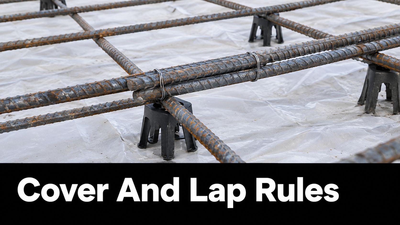
A rebar grid only works when it sits in the intended position inside the slab. Bars lying directly on soil or vapor-barrier material don't magically rise into place when concrete arrives. Workers who pull steel upward during the pour may create inconsistent elevation, disturb the surface, and still fail to place the entire mat where the design requires it.
For slabs on ground, ACI 360 guidance emphasizes roughly 1.5 to 2 inches of top cover, or 38 to 51 millimeters, so reinforcement remains effective near the slab surface and receives protection from corrosion and damage, according to the Wire Reinforcement Institute summary of ACI guidance.
Supports keep the design intact
Use chairs, bolsters, or other approved supports that can hold the mat at the specified elevation. Support selection should account for bar weight, spacing, slab thickness, worker traffic, and the force of the concrete placement. Plastic chairs may suit some conditions, while heavier supports may be needed for larger mats or demanding placements.
Before the pour, check that:
- The mat has the specified elevation. Measure from the prepared surface and forms, not by eye.
- Supports are stable. Chairs shouldn't tip, sink, or slide when workers walk across the reinforcement.
- The cover is consistent. Edge cover and top cover both matter, and thickened edges may require separate detailing.
- The bars are tied sufficiently. Ties don't need to make the mat rigid everywhere, but intersections and movement-prone areas must remain aligned during placement.
Lap splices need design information
Where bars don't run continuously, lap splices provide continuity between pieces. The required overlap isn't a universal field number. It depends on bar diameter, concrete strength, steel grade, bar location, cover, spacing, confinement, and the development provisions governing the project.
That means a contractor shouldn't accept a vague instruction to “lap the bars by a fixed distance” unless it appears on the structural drawings or comes from the responsible design professional. Splices should be staggered when required, kept away from critical locations when specified, and tied so workers can't separate the bars while placing concrete.
Steel that settles too low may still be visible after demolition, but by then the lost position can't be corrected economically.
Rebar Versus Fibers and Control Joints
The better question isn't always “rebar or no rebar?” Many slabs perform more reliably when the contractor coordinates reinforcement, fibers, joints, concrete placement, and subgrade preparation as one system.
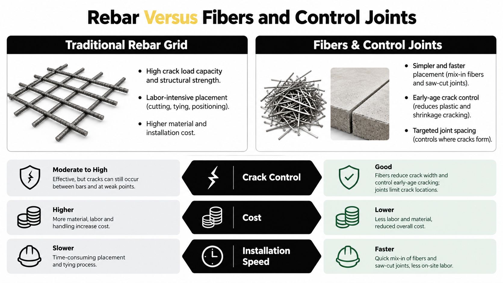
Rebar and welded wire reinforcement provide a discrete steel network that can distribute forces and hold structural cracks tighter. Fibers disperse throughout the concrete, which can simplify handling and support early-age crack control. Macro-synthetic fibers and steel fibers aren't interchangeable with a structural rebar design in every application, especially where concentrated loads or engineered flexural reinforcement govern.
What each approach does well
| Approach | Strength | Limitation |
|---|---|---|
| Traditional rebar grid | Provides a defined load-distribution and crack-control network | Requires careful support, tying, and placement |
| Welded wire reinforcement | Can distribute reinforcement across a slab when properly supported | Doesn't work as intended if it ends up on the ground |
| Macro-synthetic fibers | Disperse through the mix and can simplify reinforcement handling | Must be selected and dosed for the application, and they don't remove joint requirements |
| Steel fibers | Add distributed reinforcement within the concrete | Don't eliminate timely control joints or replace every engineered bar layout |
| Hybrid system | Combines distributed fibers with targeted bars or mesh | Requires coordination so the materials serve different purposes rather than duplicating cost |
Technical material from Solomon Colors on fiber reinforcement and jointing emphasizes that joint spacing should still be designed as if the slab were unreinforced. It also explains that fibers control cracks rather than eliminate them and that macro-synthetic systems can support significantly longer joint spacing in suitable designs.
Joints still control where movement appears
A control joint gives drying shrinkage and temperature movement a planned location. If the contractor waits too long to saw joints, the slab may crack randomly before the planned relief is created. Steel fibers don't remove that need, and rebar doesn't excuse poor joint timing.
A hybrid strategy may make sense for a large driveway, commercial floor, or property with difficult access. The right combination depends on loads, thickness, joint plan, finish requirements, and the engineer's design. Closer rebar spacing isn't a substitute for a stable base and a timely jointing operation.
Physical Placement and Tying Best Practices
The layout on paper must survive the job site. Start by confirming the forms, dimensions, openings, thickened edges, drains, sleeves, and planned joints before placing steel. Mark the grid with chalk lines or measured offsets so the first bars establish a consistent pattern rather than forcing workers to estimate each intersection.
Set the bars in both directions when the design calls for a two-way mat. Tie intersections often enough to prevent walking and concrete placement from shifting the grid. The objective isn't to weld the entire mat into an immovable frame. It's to keep the bars aligned, supported, and at the designed elevation until the concrete has surrounded them.
Keep concrete moving around the steel
Fresh concrete needs a clear path around every bar. Check the gap between adjacent bars, especially where laps, bundled pieces, edge bars, dowels, and penetrations create congestion. If the aggregate can't pass through the reinforcement, vibration may not remove trapped air and the finished slab may contain voids.
A reliable sequence looks like this:
- Prepare the base and forms first. Remove loose debris, verify elevations, and correct soft areas before the mat hides the work.
- Place supports before the steel. Use stable chairs or bolsters suited to the mat and slab conditions.
- Lay the first direction. Keep the bars at the specified edge offsets and align them with the planned grid.
- Lay the crossing direction. Check spacing with a tape or marked gauge rather than relying on visual judgment.
- Tie movement-prone intersections. Secure edges, laps, openings, and areas where workers will step during the pour.
- Recheck after access is created. Walking boards or designated paths can reduce damage to the prepared mat.
The residential poured concrete service information is a useful reference point for owners comparing installation approaches and asking contractors how they support reinforcement before placement.
Don't let the finishing crew pull a settled mat upward as a routine correction. That movement can bend bars, disturb chairs, alter cover, and leave sections at inconsistent depth. Fix the support and elevation before the truck arrives.
Cost Implications and Repair Thresholds
Reinforcement and slab thickness shape both the bid and the repair risk. Wider bar spacing can reduce steel and labor, but it distributes cracks less effectively. Tighter spacing or a thicker slab costs more to place, yet may suit driveways exposed to heavy vehicles, turning loads, weak support, or uncertain drainage.
For Atlanta driveway work in 2026, reported pricing commonly ranges from $8 to $14 per square foot before unusual excavation, drainage, demolition, or decorative upgrades. Standard residential projects are often reported at $3,000 to $8,000, while reinforced or thicker driveways are often quoted at $10 to $17 per square foot, according to the Atlanta concrete driveway cost guide for 2026.
| Driveway Type | Cost per Sq Ft (2026) | Expected Lifespan |
|---|---|---|
| Standard concrete driveway | $8 to $14, before unusual site or decorative work | At least 30 years, per independent Atlanta concrete driveway guidance |
| Reinforced or thicker driveway | $10 to $17 | Depends on design, support, drainage, joints, and maintenance |
A service-life estimate is not a guarantee. Poor drainage, unstable Atlanta soil, neglected joints, deicing exposure, overloaded pavement, and inadequate curing can shorten the slab's usable life, regardless of the reinforcement grid. Price the work around those conditions rather than treating spacing as an isolated upgrade.
Know when repair stops making sense
Concrete driveway repair guidance separates small cracks or holes under 1/4 inch from larger defects. Small damage may respond to patching or filling. Cracks or holes over 1/4 inch, along with spalling, scaling, discoloration, or structural damage, can shift the practical choice toward resurfacing or replacement.
Repair only makes financial sense when the underlying support remains stable. A surface patch will not correct settlement, poor drainage, repeated movement, or a failing base. Before approving work, identify the cause and confirm whether the defect is localized or spreading.
Compare more than the cheapest reinforcement grid. Ask whether the design matches vehicle loads, whether joints and drainage are included, and whether bar elevation will be documented before concrete placement. Concrete and masonry repair services may be relevant when an existing driveway has localized defects and its base remains serviceable.
Pre-Pour Inspection and Verification Checklist
The last inspection should happen before concrete covers the work. Once the pour begins, correcting a spacing error, missing bar, sunken chair, or misplaced opening becomes disruptive and expensive. The property owner, contractor, and inspector should compare the field condition with the drawings and the agreed scope.
Verify the reinforcement
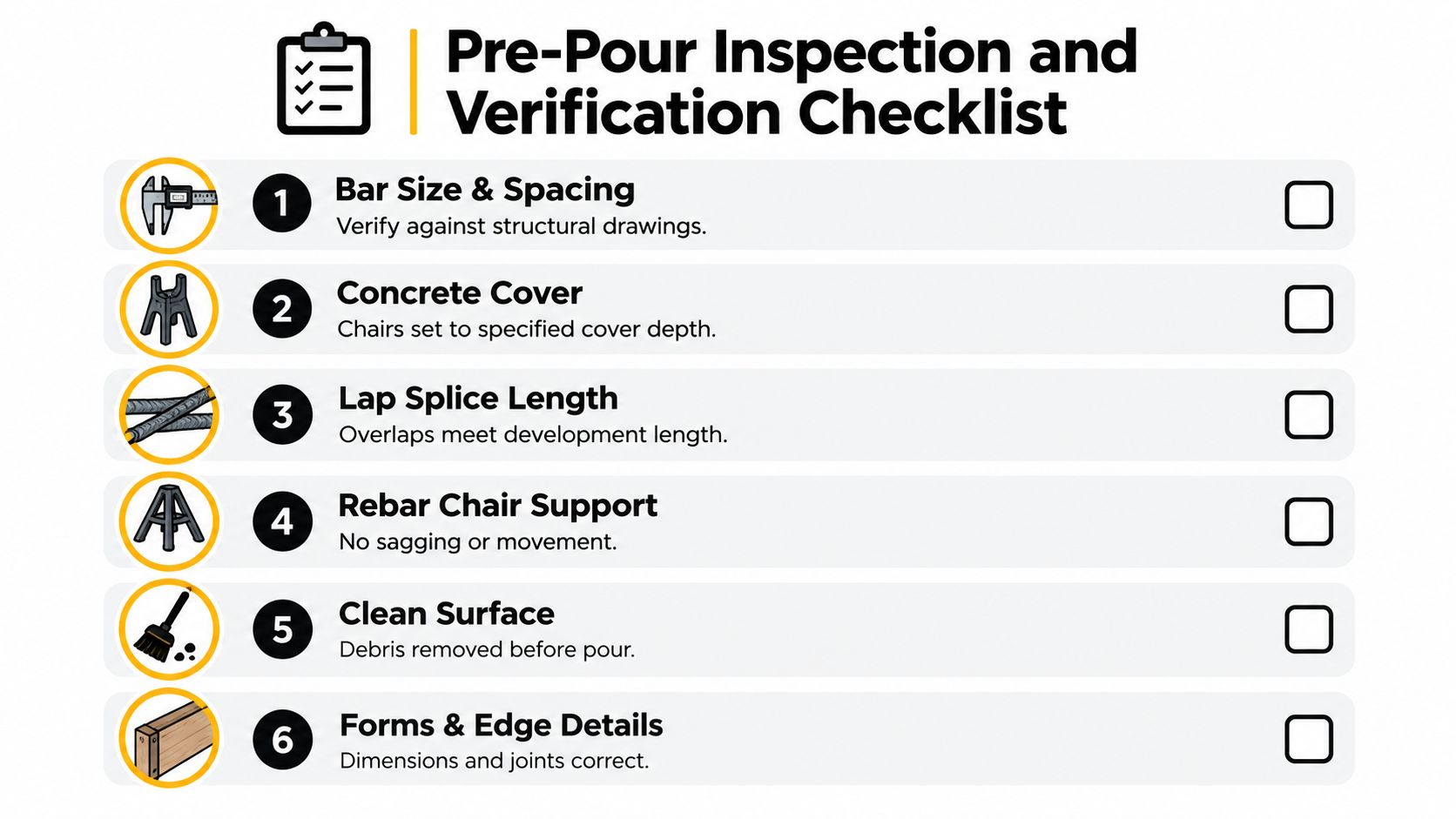
- Bar size and spacing: Measure the actual diameter and center-to-center spacing against the structural drawings. Confirm the applicable maximum, whether the layout is one-way or two-way, and whether concentrated-load areas have special details.
- Concrete cover: Check top, edge, and thickened-section cover with a scale or cover gauge. For slabs on ground, verify the specified top-cover range rather than accepting a mat resting on the base.
- Lap splice length: Compare every splice with the project detail or engineer's instruction. Don't substitute a guessed overlap.
- Chair support: Walk the access path carefully and look for sagging, tipped chairs, unstable bases, or bars touching the subgrade.
- Clean surface: Remove mud, loose debris, standing water, and materials that could interfere with concrete placement or bond.
- Forms and edge details: Confirm dimensions, elevations, isolation details, penetrations, drains, thickened edges, and joint locations.
- Subgrade condition: Verify that the base is compacted and suitably prepared for placement. Correct soft or wet areas before the mat is accepted.
- Pour logistics: Decide where workers will stand, how the concrete will reach the forms, and how vibration will be performed without displacing the reinforcement.
A final photograph of the complete mat can help document the pre-pour condition, but photographs don't replace measurements. Mark any approved field changes on the project record so the completed slab has a clear installation history.
Use the following video as a visual supplement for reinforcement inspection and placement:
The durable answer to rebar spacing for concrete slab isn't a universal grid. It's a coordinated decision based on slab thickness, loads, support, cover, clear spacing, joints, and the reinforcement system selected for the site.
Atlanta Concrete Solutions can review driveway thickness, reinforcement layout, joint planning, drainage, installation, resurfacing, and replacement needs for properties in the Atlanta metro area. For a project-specific assessment and quote, visit Atlanta Concrete Solutions and discuss the slab conditions before concrete is ordered.